How to build the ultimate MIDI Controller
You need:
- Old analog Mixer (e.g. Mitec 1602) 25€
- 16 multiplexer CD74HC4067, 16 channels each, 20€
- 4 shift registers 74HC595, 8 bit each, 10€
- Capacitors (20 for the channels)
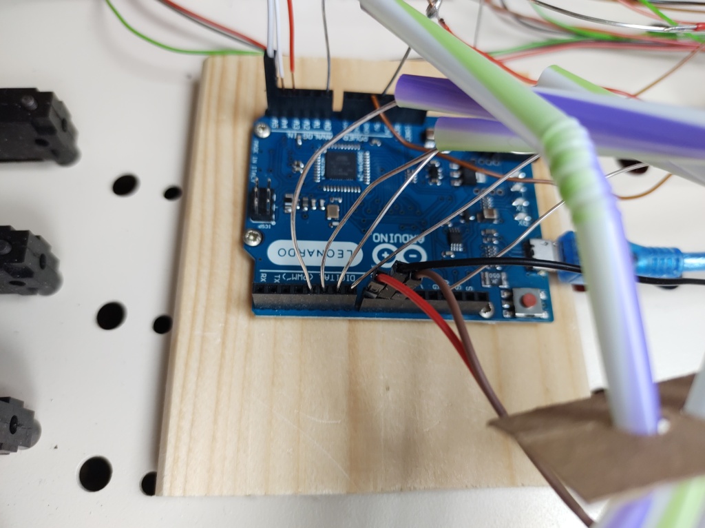
- Arduino Micro without headers, 20€
- Midi Shield, 10€
- 3 Step down voltage regulator LM2596, 10€
- Neutrik Usb Connector
- 2 Neutrik Midi connectors
- Micro USB cable
- Midi cable (5 Pin DIN)
- Wire
- Silver coated copper wire
- Ironing tin
- VU meter driver board (optional) 10€
- VU meter replacement light bulbs
- Mixer light (optional)
- Replacement potentiometers Radiohm CIP20C-KS
Start with an old analog Mixer. Most stuff from early 80s should be good. Do a pre-check, whether it uses a single PCB (not good) or individual cards per channel (good). Mitec, dynacord, etc. are good candidates.

Open it, disassemble everything. Do an outside cleaning. Remove potentiometer tops. Wash gently. Remove wooden side panels. Clean and apply wood conservation. Disconnect the individual channel cards.
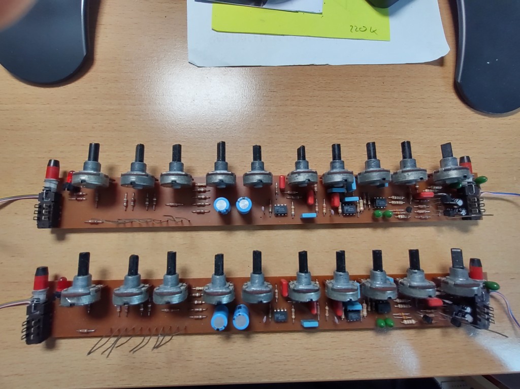
For each card, unsolder everything except the potentiometers and switches.

Reverse engineer the card layout. Find good rails for ground and +5V. Find good spots to connect each potentiometer.

Per audio channel, there are 11 analog and 2 digital inputs. We can use the 3 remaining channels on our 16 channel multiplexers for inputs from masters and effects.

I placed capacitors for voltage stabilization. It is strongly encouraged to test the individual channel cards. Having a dedicated Arduino at hand helps a lot. I was able to spot wiring issues, flaky potentiometers and electrical shorts in this step.
We will (re)use a bus layout for voltage, signal and multiplexer selection. A single signal wire is sufficient as we will enable individual multiplexers from the shift registers.
This allows us to read up to 16*16=256 values using a single Arduino with 2*8bit shift registers and 16 multiplexers. It requires 3 digital pins for the shift register, 4 digital pins for multiplexing and 1 analog pin to read back the values.
The LEDs per channel will be driven by the second set of shift registers.
Measure the PSU. You most likely find +12v, -12v and possibly others. Use the step down voltage regulator for nice +5v for Arduino, +15v for the VU meter and +12v for optional mixer light.

I first planned to use the original amplifier to drive the VU meter. It turned out, however, that it requires too many different voltages and valid signals, so I resorted to a driver board. In some comment I found suggested tuning parameters (input voltage, resistors for meter and light) and used that.

The good thing about old mixers is, you have plenty of room to build in stuff.
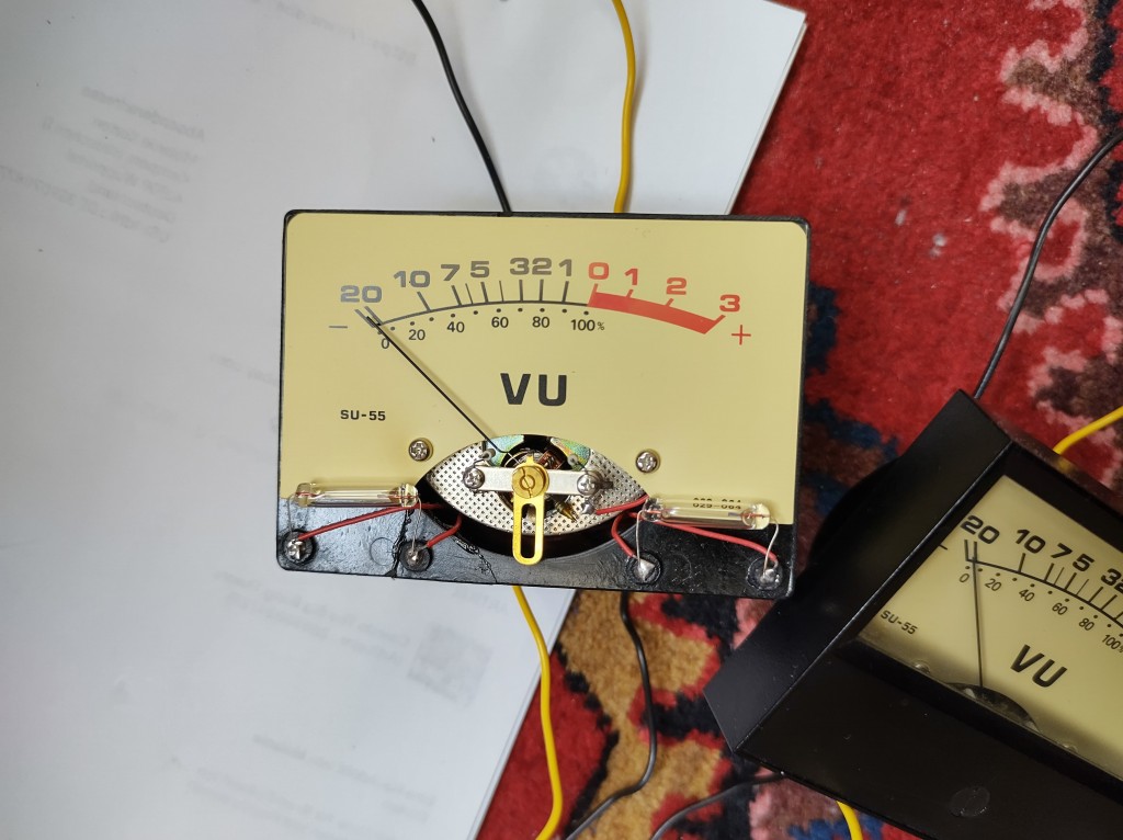
One of the VU meters required new light bulbs. These have become somewhat expensive. People have started to fit in LEDs. For now I stick with the original bulbs. The outer plastic frame was also cracked and could be fixed with glueing things back together.
I replaced three of the original Nautic XLR connectors with 1 USB and 2 MIDI connectors. The size and measurements haven’t changed at all in 40 years.
So let’s start with software.
Signal conversation: on Arduino, analog read gives a 10 bit value (0…1023). Potentiometers are either linear or logarithmic. We map that to 7bit linear. For linear potentiometers we simply divide by 8, for logarithmic, we use (log10)² * factor.
Debouncing: analog values are jumping so we do the following. We store 7bit values in a 8bit char. Char stores values from -128 to 127. We use positive values for when we increase and negative values when decreasing. When we change direction, we apply a small upfront threshold. This allows fine granularity when moving in the same direction and avoids bouncing.
I implemented several play modes. In play mode 1 each channel sends on that midi channel. As we have 11 potentiometers, I went for basic stuff, such as volume, balance etc. From the lowest MIDI CCs.
In play mode 2, there are 2 columns per MIDI channel with a total of 8 active channels. Similar approach for play modes 3 to 10.
Play mode 11 is a drum machine mode. Each row represents a single instrument.
Play mode 12 is a 5 instrument sequencer.
This covers the following group of devices
- DAW controller (similar to Doepfer Drehbank, Regelwerk, DJ techtools MIDI fighter twister, Faderfox PC12, Icon Qcon, Presonus Faderport, Akai Midimix, Evolution UC33, Livid Elements, …)
- Sequencer (similar to ARP Sequencer, Korg SQ64, Doepfer Schaltwerk, Manikin Schrittmacher, Doepfer Darktime, MAQ 16, …)